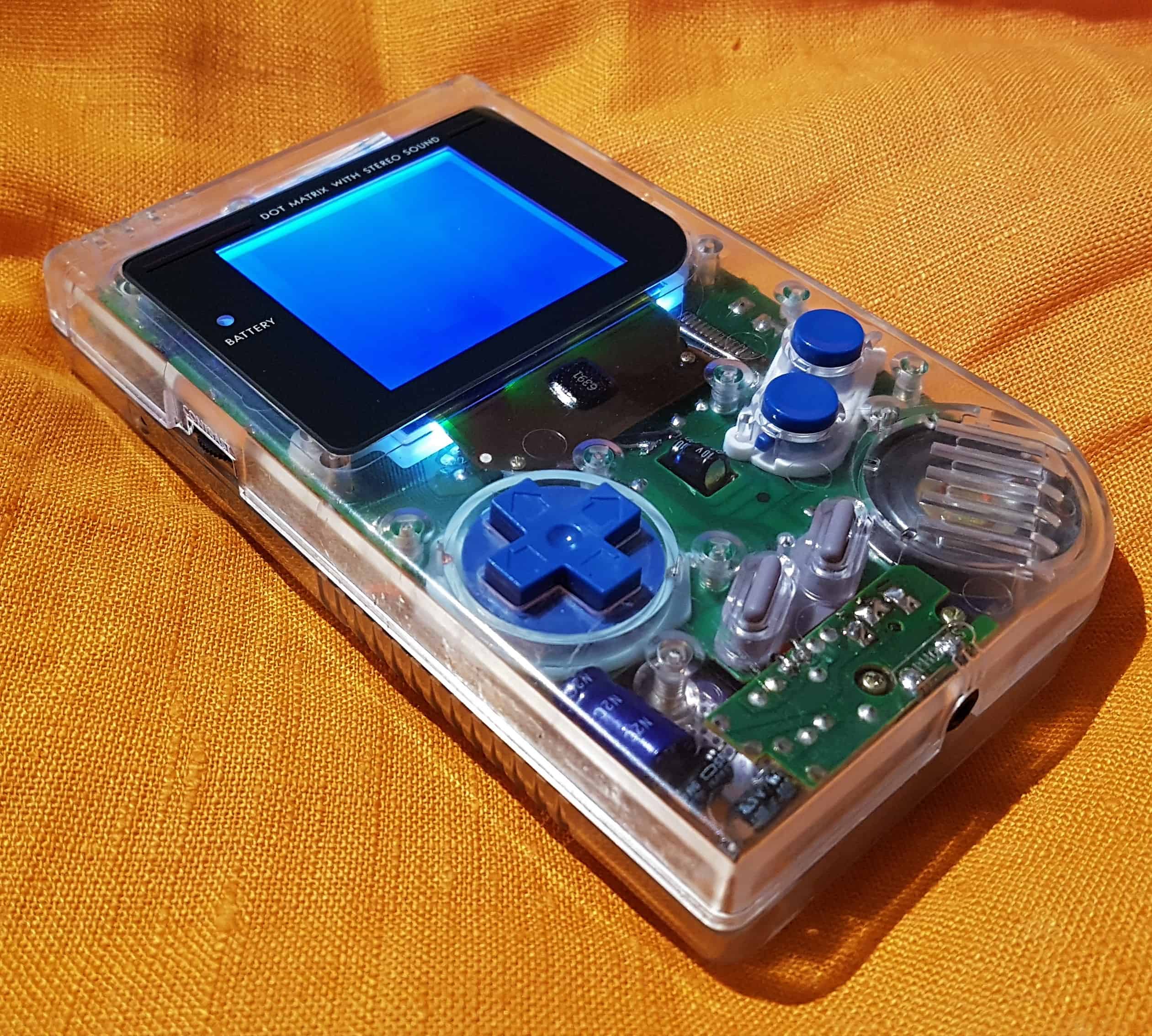
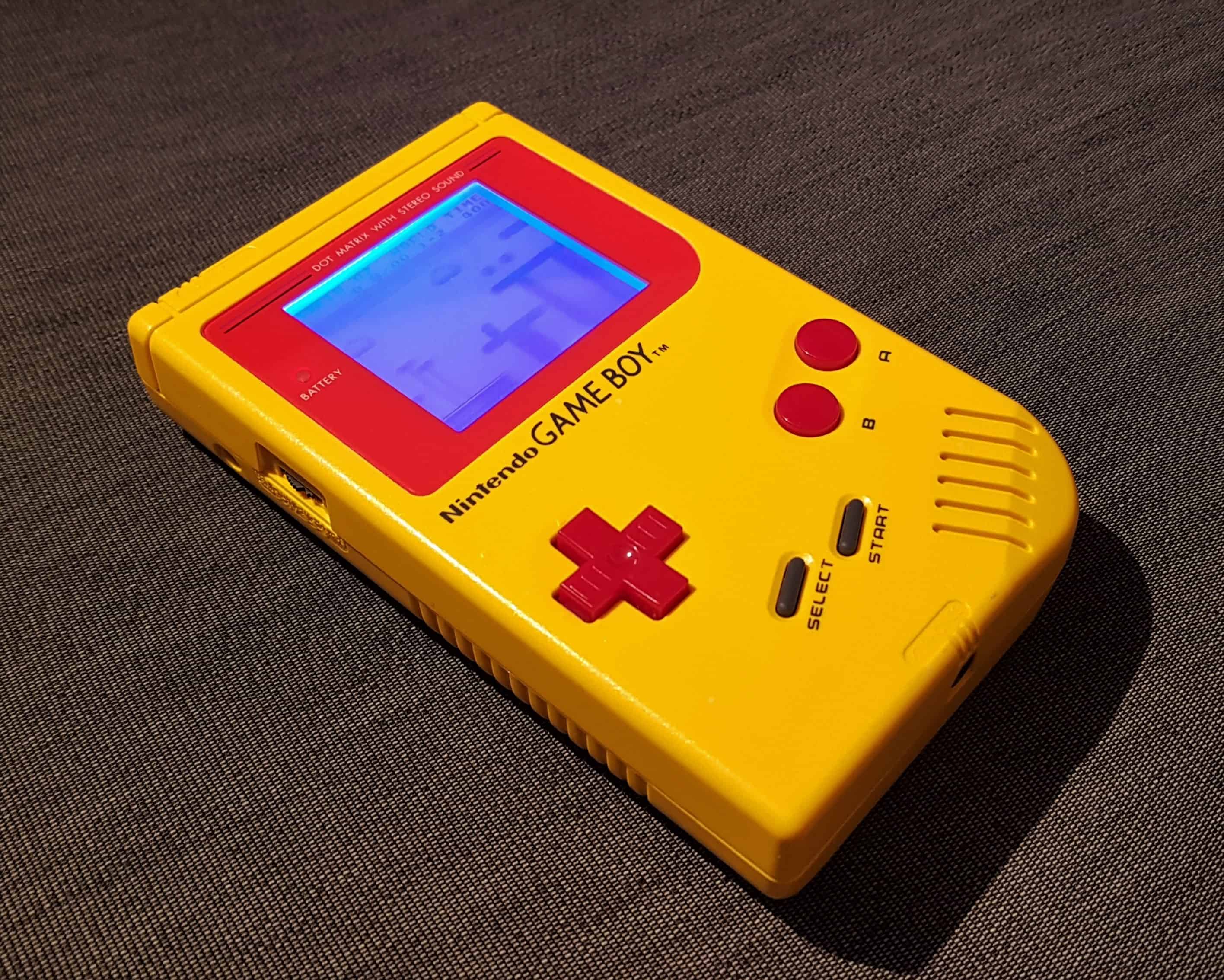
Game Boy DMG-01 modding step by step guide
Last update: January 5, 2022
 Good news, everyone. I wrote a book about Game Boy modding and Repairs.
The thing is, I was going to update this page since it’s the single most visited page on my site. But as I kept writing it became larger and larger, because I wanted to cover all the tips and tricks that I have learned over the years. After a while, I had written so much and taken so many new photos that I got the idea to turn it into a book instead. So there you have it.
It’s called Game Boy Modding and Repairs: A step-by-step guide for beginners. I hope you want to support me and check it out. It’s an e-book that works on your mobile phone, tablet, Kindle, etc and it’s only $10.59.
The step-by-step guide
Here is a step-by-step guide for modding the classic Game Boy DMG-01. Instead of going into details about the obvious mods, like replacing the screen (cover), buttons, and silicon parts, I will focus on the more technical aspects of modding. Got any questions not covered in this tutorial? Check out my book, or go to my official Facebook page, click like and ask me. Also, don’t forget to check out my music on Spotify.
Procedures
How to install a backlight
How to install a bivert chip
How to do the Prosound to headphones mod
How to do the bass mod
How to do the Decoupling capacitor on the powerstrip mod
Final results
What you need before getting started
- Game Boy DMG-01
- Soldering iron or Soldering station, preferably one with variable temperature
- Solder wire
- Desolder braid
- Scalpel
- Tri-point Y1 screwdriver
- Cross screwdriver
- Wire
- Flush cutter
- Isopropanol
- Cotton swabs
- Polishing cloth
- Game Boy Backlight kit
- Game Boy Bivert chip
- 1 Electrolytic capacitor 1000uF, 10V minimum
- 2 Electrolytic capacitors 10uF, 10V minimum
How to install a backlight
1. Remove the polarizing film and reflective layer on the backside of the screen
Open up your Game Boy and remove all the screws from the two boards, then pull out the ribbon cable connecting the two halves.
Remove the two small screws below the screen. Carefully lift up the screen using a screwdriver or a small spatula tool in the little notch in the top of the plastic frame. There will be a little resistance because of two small adhesive pillows on the inside. When you have pulled up the screen enough to see them both, carefully remove them with a pair of tweezers.
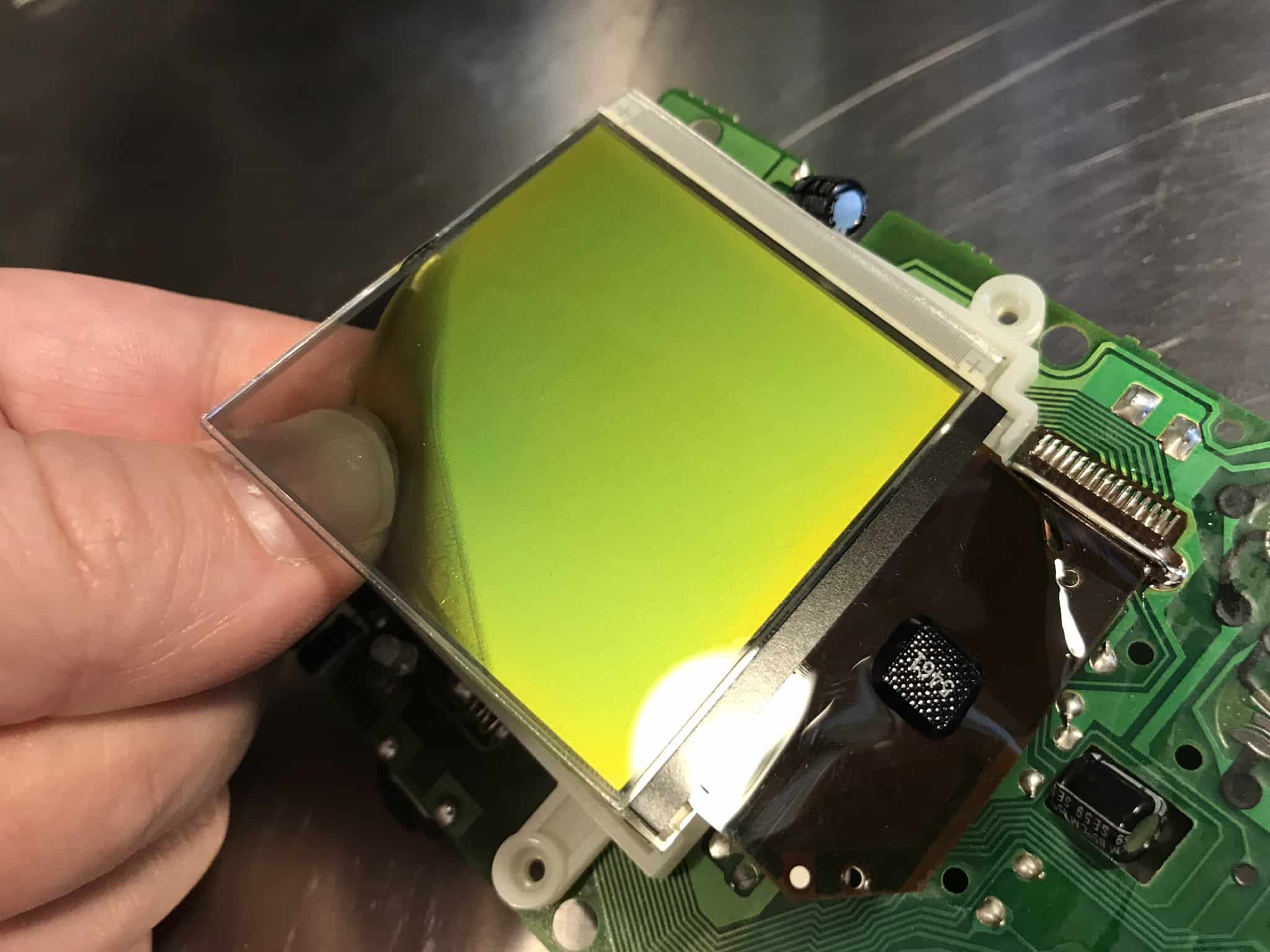
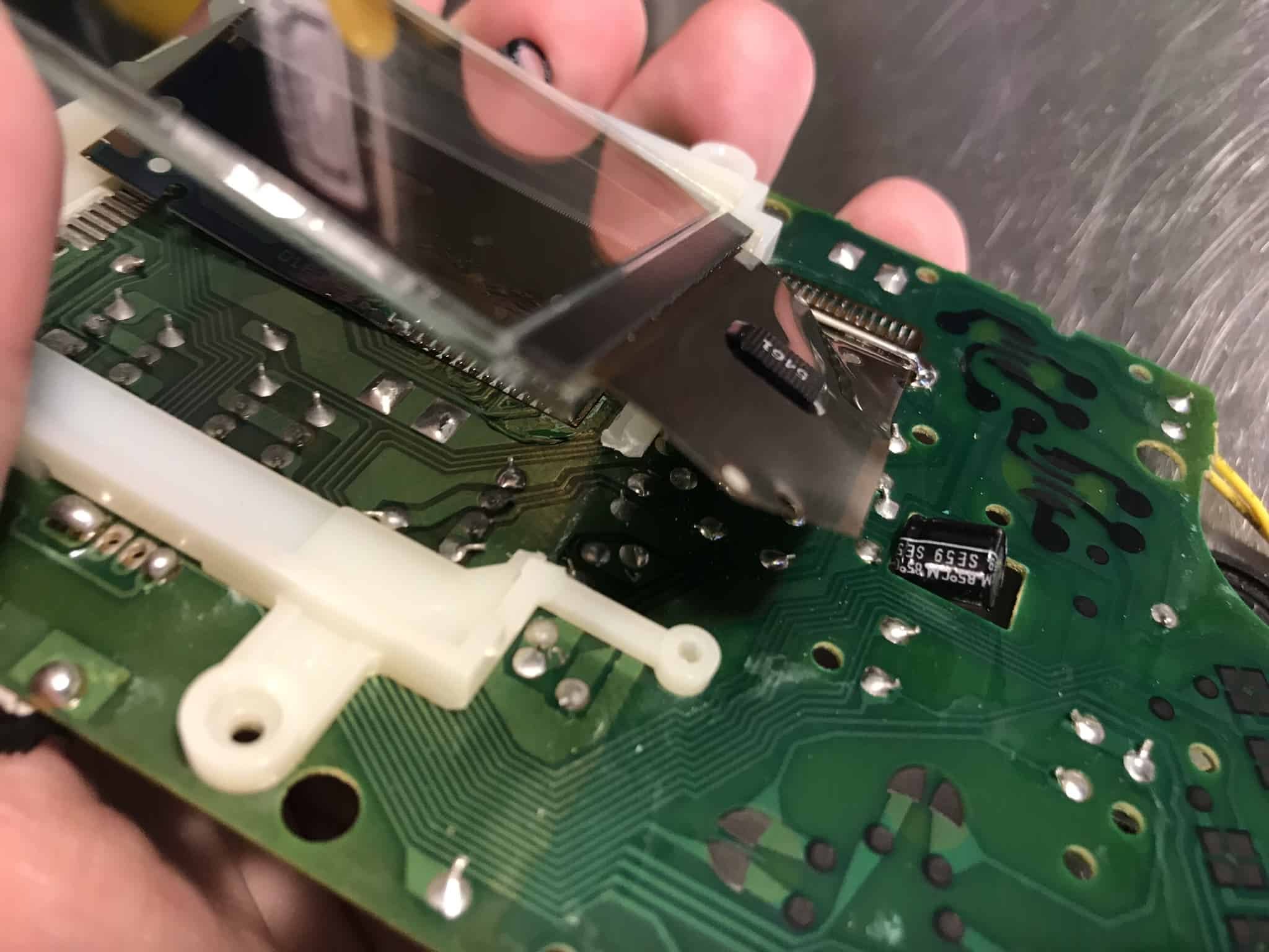
Now you are going to pull off the polarizing film and reflective layer while trying not to break the screen and the solder points underneath the screen. This part can be a bit tricky so if it’s your first time I recommend first try it out on the screen that is already broken beyond repair, for example, one with screen cancer.
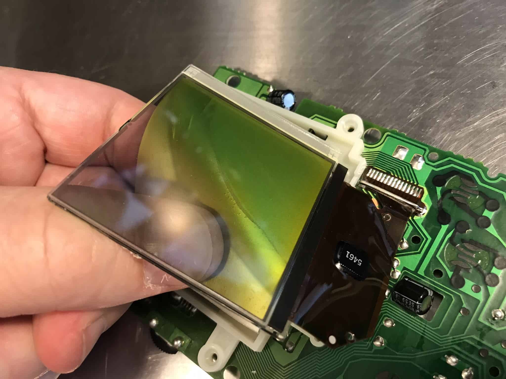
The polarizer and reflective layer are glued together. You will remove both of them in one take by inserting a sharp knife like a scalpel in the top left corner. The trick not to scratch the screen is to press in the knife just a few millimeters where the layers meet the glass. Then use the knife, carefully pushing the material away from the screen so that it opens up a corner big enough for you to grab with your thumb and index finger. Once you can grab it, start slowly pulling away more by moving your thumb inwards and along the sides of the screen.
The process of removing the polarizer and reflective layer can be anything from quick and simple to very hard, depending on the stickiness of the glue. I have found that the newer models of the DMG-01, the so-called Play it loud editions usually are the easiest ones to work with, in terms of removal time and amounts of glue that are left to be dealt with afterward.
Try not to exert too much force on the screen so that it bends. If it bends too much it will snap and become unusable. That happened to me once. That popping sound is not something I would like to hear ever again when doing a backlight mod… Also, try not to put too push the screen too much away from the frame as this may damage the fine solder points under the screen. More about that later.
Here you can see how I have slowly and carefully worked my way towards the other side of the screen.
2. Clean the screen
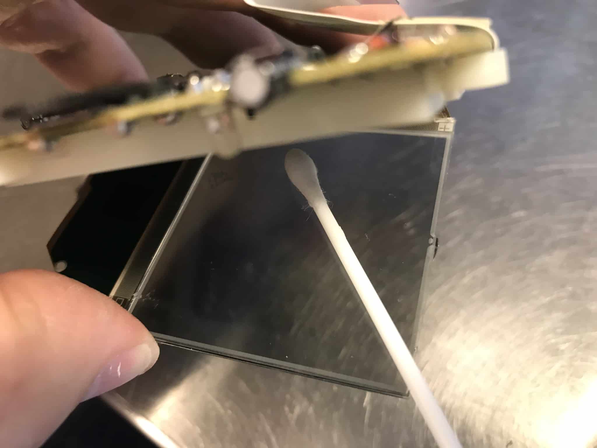
With the polarizer layers finally off, in best case scenario there is almost no glue on the screen. The cleaning process can take anything from 10 minutes to an hour depending on the amount of glue left on the screen.
Use plenty of Isopropanol and cotton swabs in a circular motion to loosen up the glue and then drag the bits of glue off the screen. You may have to go through three to twenty cotton swabs depending on how much glue is left. The goal here is to remove all of it and that may take some time if you are unlucky.
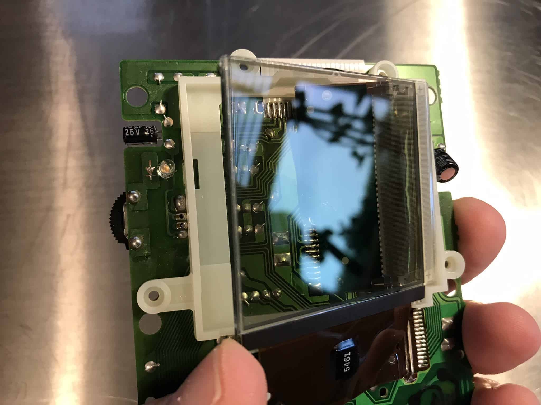
When all the glue has been removed, there will still be some residue from the isopropanol on the screen. Clean that off with a very fine polishing cloth, like the one you would use to polish a car. Do not use toilet paper or something like that since that could scratch the inside of your screen. I use a technique where I apply some of my breath to it and quickly and carefully clean with the polishing cloth.
When you have cleaned and polished the inside of the screen it should look like this. You should see no streaks, dots, smudges or fibres left from the cotton swabs, even if you hold it up to the light.
3. Cut a hole in the plastic frame for the backlight connector
Use a small wirecutter tool to cut off a bit of the plastic big enough for the backlight connector to fit.
4. Solder the resistor and wire
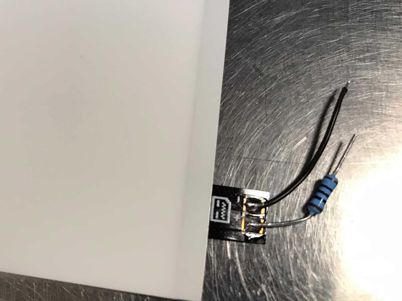
I always use backlights from Deadpan Robot. It comes with a resistor that needs to be soldered to the connector where it says plus (+).
I have found that doing it like depicted in the picture below is the easiest and fastest way. Solder the resistor directly to the connector on the backlight and then bend it almost 90 degrees to the right.
5. Install the backlight and solder the resistor and other wire to the board
Install the backlight by sliding it into the plastic frame under the screen. Remove the protective sheets on the polarizer and slide it in over the backlight, making sure you don’t scratch it. On the backlight type I use there is a blue stripe on the polarizer which indicates its backside. Also, make sure the screen becomes dark blue after you have inserted the polarizer. If it’s not dark blue then take it out again, flip it 90 degrees and insert.
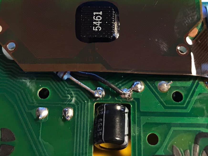
Now solder the resistor and the black wire to the board, like in the image below. It’s easier if you use a pair of tweezers to hold them in place as you solder. You may need to apply some new solder to make them stay.
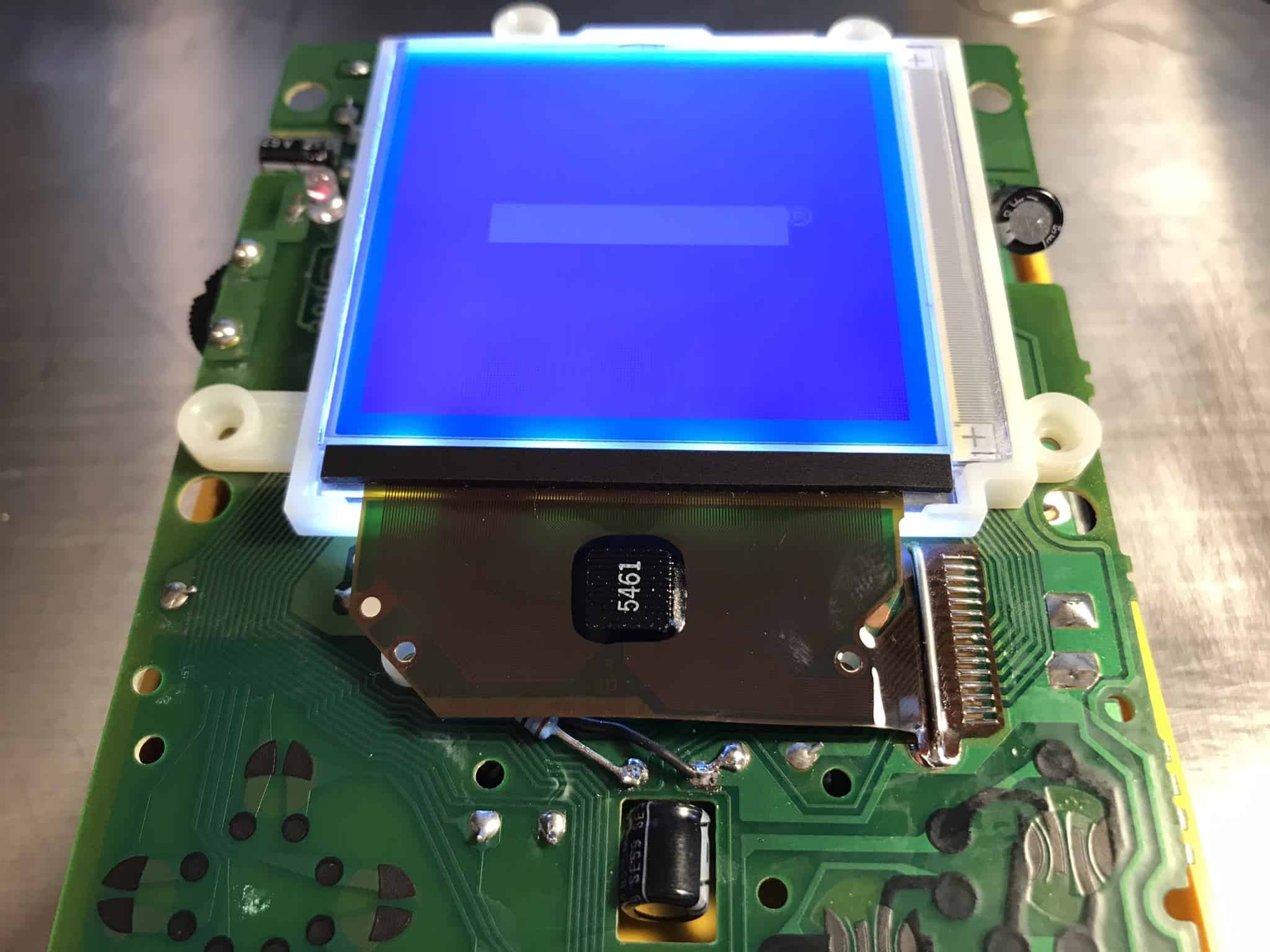
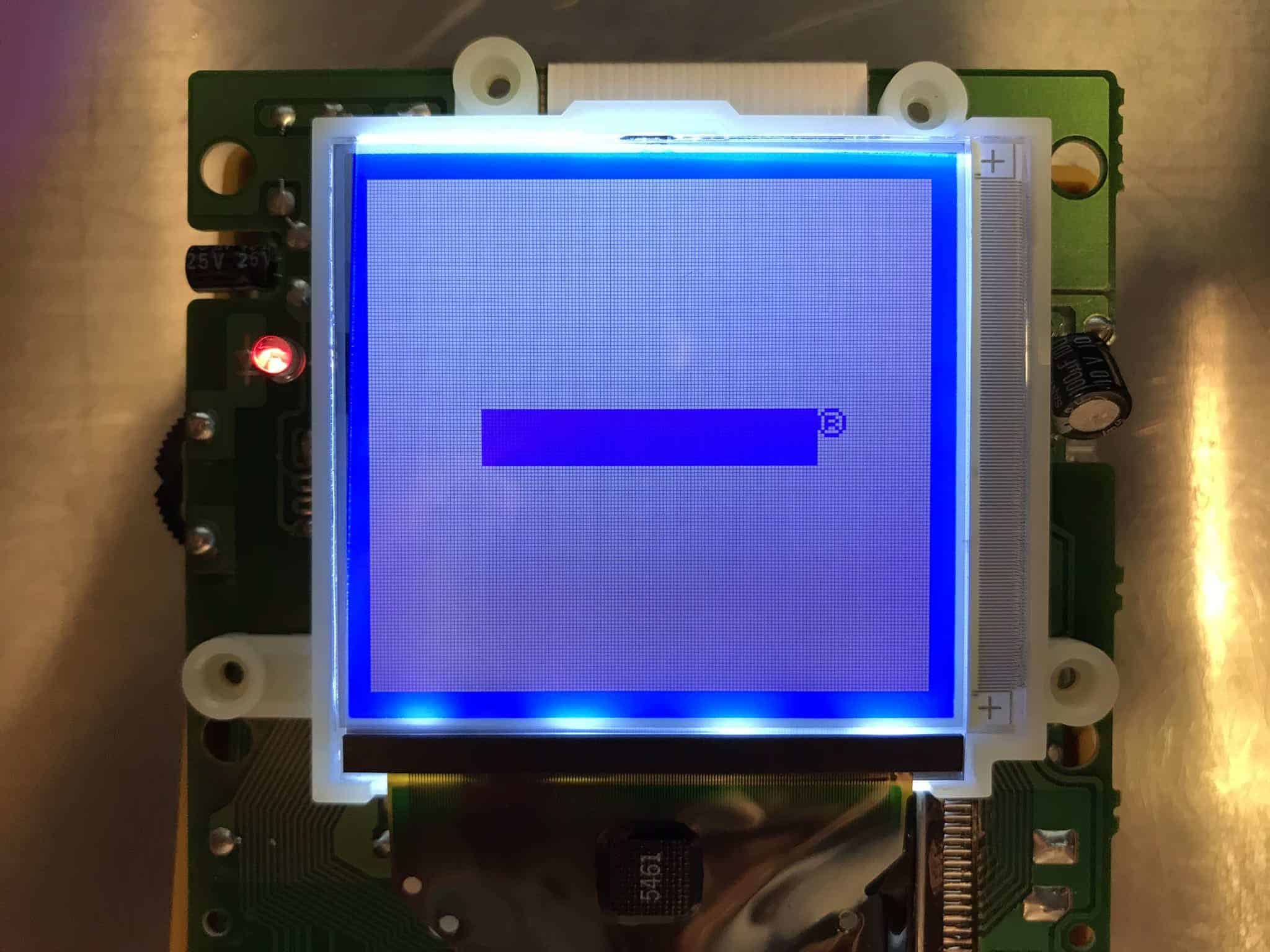
Reconnect the CPU board with the display board, put them in your case without screwing everything back together, insert batteries and start up the Game Boy to see if it’s working. If it doesn’t look anything like the image below then something is wrong.
How to install a bivert chip
Now it’s time to put in the bivert chip. This will make the Game Boy video look crispier and with less ghosting. The bivert chip is pre-installed on a tiny circuit board that you just solder in place.
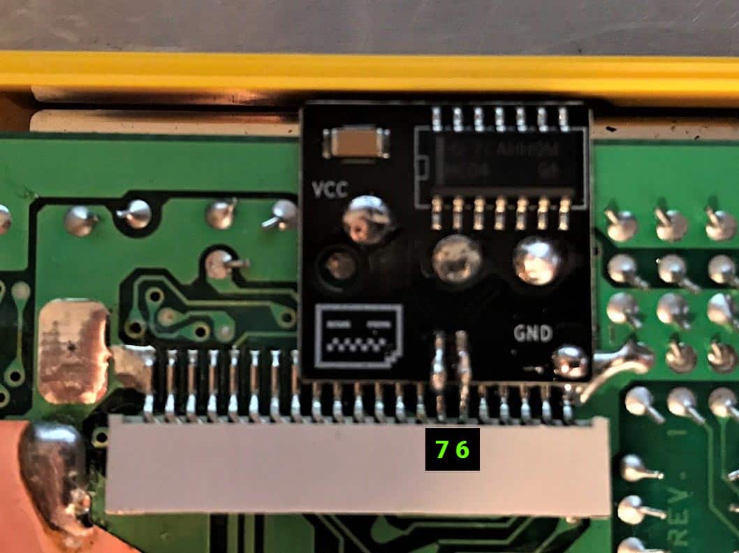
1. Desolder pins 6 and 7 on the video connector
Locate the video connector and desolder pins 6 and 7, as shown in the image below. I have tried different techniques on how to desolder them without breaking anything. I’ve found that the quickest way is to press a scalpel to one of the solder joints, then hold the tip of the soldering iron on it, while I gently prying the scalpel underneath it. The goal here is to bend the two pins upwards and break their existing connection to the board.
2. Solder the pins to the bivert chip and the other solder points
When both pins 6 and 7 are de-soldered and slightly bent upwards I put in the bivert chipboard and re-solder both pins to it. It’s pretty small and tricky so you may need to use a magnifying glass here. When both pins are soldered I then continue with the other four points on the bivert chipboard.
3. Reconnect the Game Boy
It’s time to see if the video is still working. If it looks like the image below then you are in the clear.
How to do the Prosound to headphones mod
With the pro sound mod, you get a better-sounding Game Boy. It’s done by sending the sound directly to the headphones, bypassing some internal circuitry that otherwise adds unwanted noise.
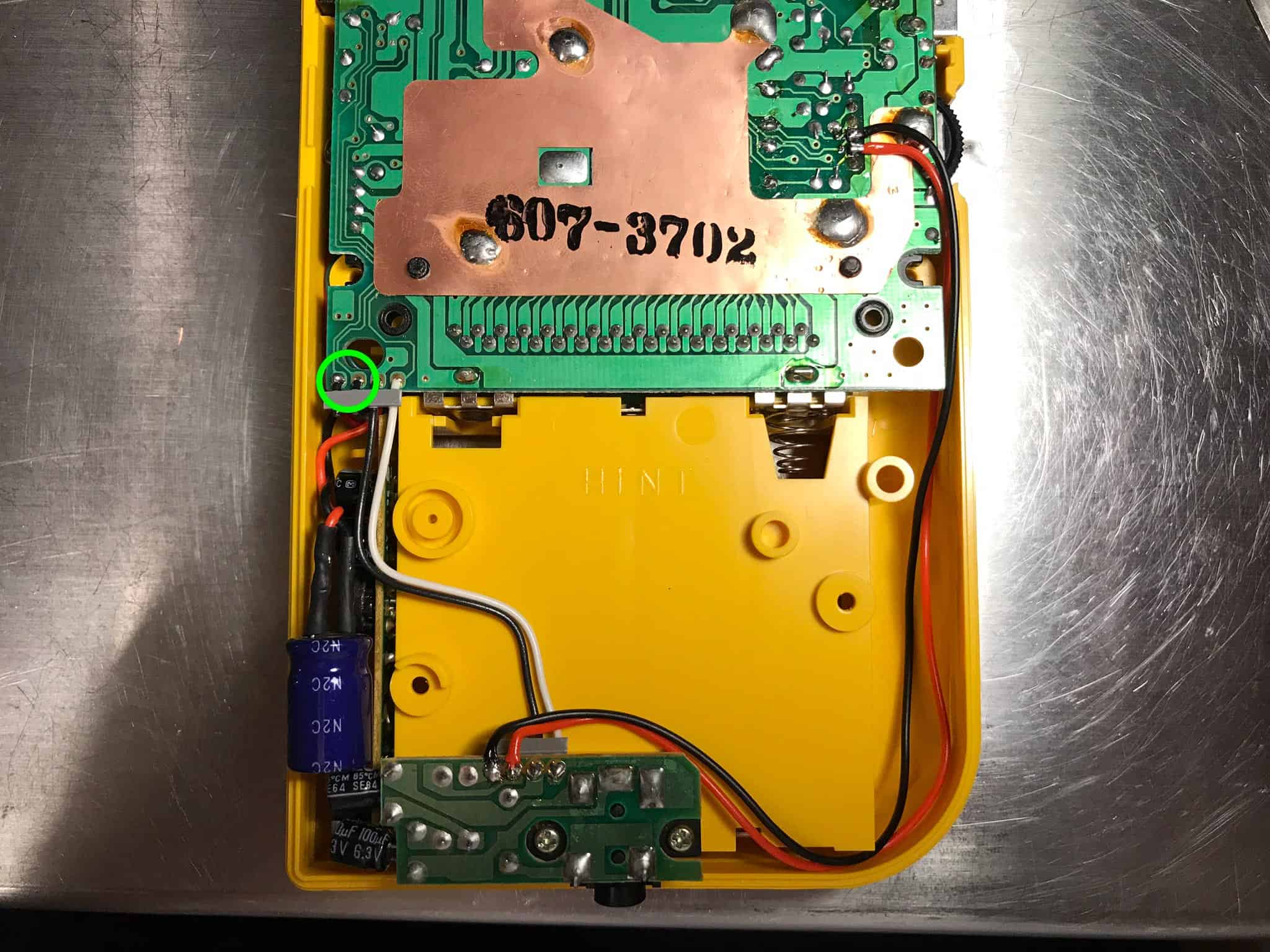
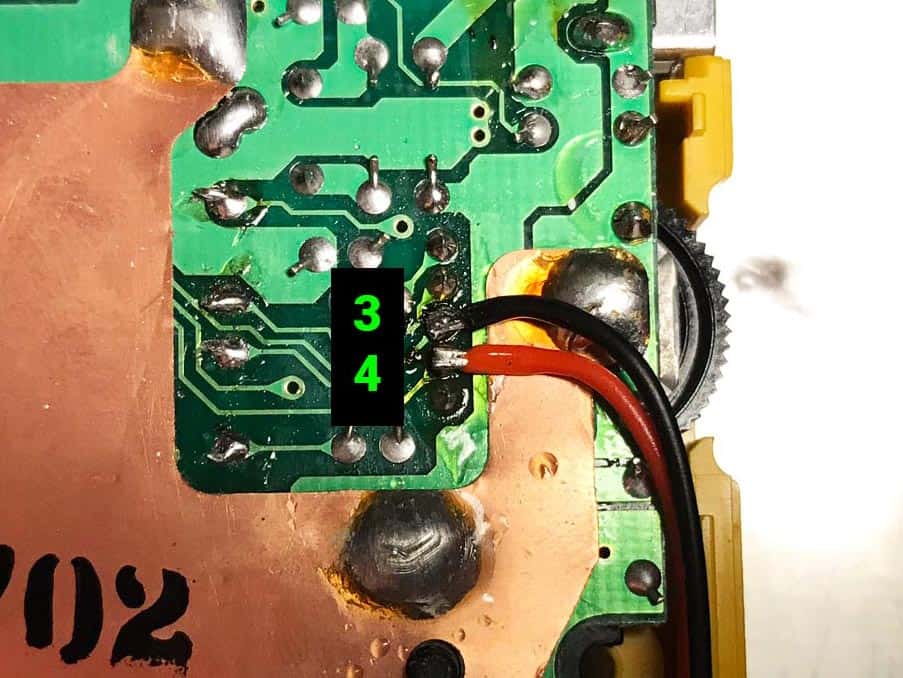
This one is so easy I won’t write a step by step for it. Just cut and remove the two black wires shown in the image. Then solder two new wires as also shown in the image.
Solder the black wire to solder point number 3 and the red wire to solder point number 4. They are pretty small so what I do first apply some solder to them. I keep the tip of the wires pretty small and apply solder to them before soldering them onto the board. Be careful not to hold the iron for very long on the solder points or you may break them. They are very tiny and delicate.
When done, reconnect the Game Boy and start it up with a game. Listen to the sound and try lowering and boosting the volume to make sure there are no crackles and other strangeness going on soundwise. Also, try out with the headphones to make sure you have sound there as well.
How to do the bass mod
The bass mod adds a bit of sub-bass in the lower ranges, like 40-50 Hz. You would typically need a good pair of headphones or a sub to notice the change, but it will definitely sound beefier on a club sound system.
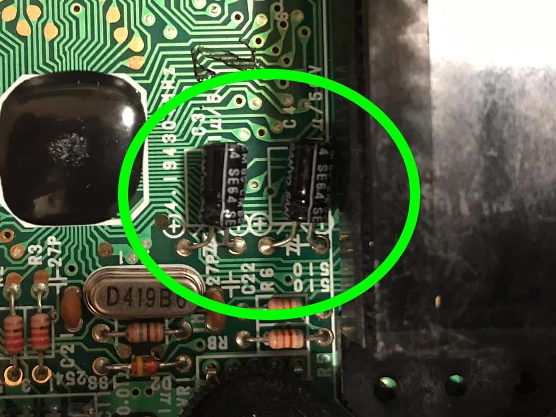
1. Locate the two 1 uF capacitors on the CPU board
You will find them close to the volume wheel.
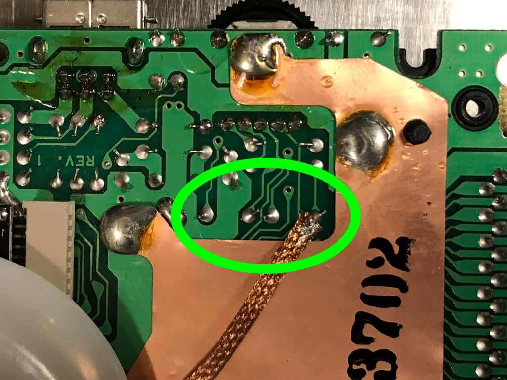
2. Desolder the capacitors
Turn the board and desolder the two capacitors. The easiest way is to use a desoldering braid. Make sure it’s not too big. I think the one in the image above is something like 2 – 2.5 mm wide. If possible, lower the heat on your solder station a bit, place the braid on a solder point and put the solder iron over it. These points are delicate and pretty easy to break if you apply too much heat for too long, so try to be careful with this one.
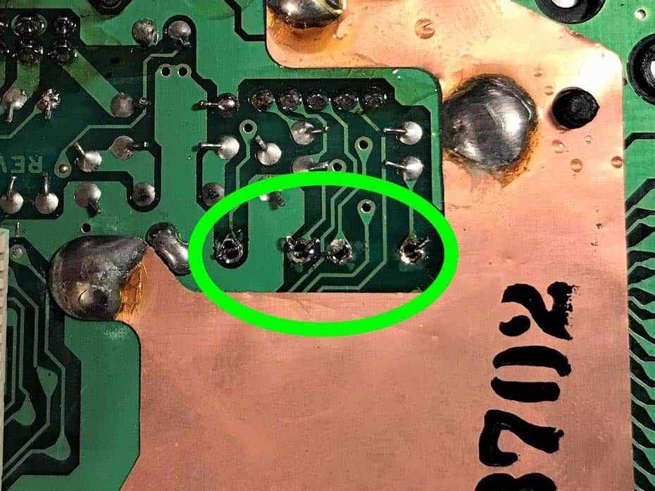
3. Remove the old capacitors and solder new ones
When desoldered, it should look something like the image above. Turn the board, remove the old capacitors and put in two 10uF instead, making sure to put the leg for + where it says + on the board.
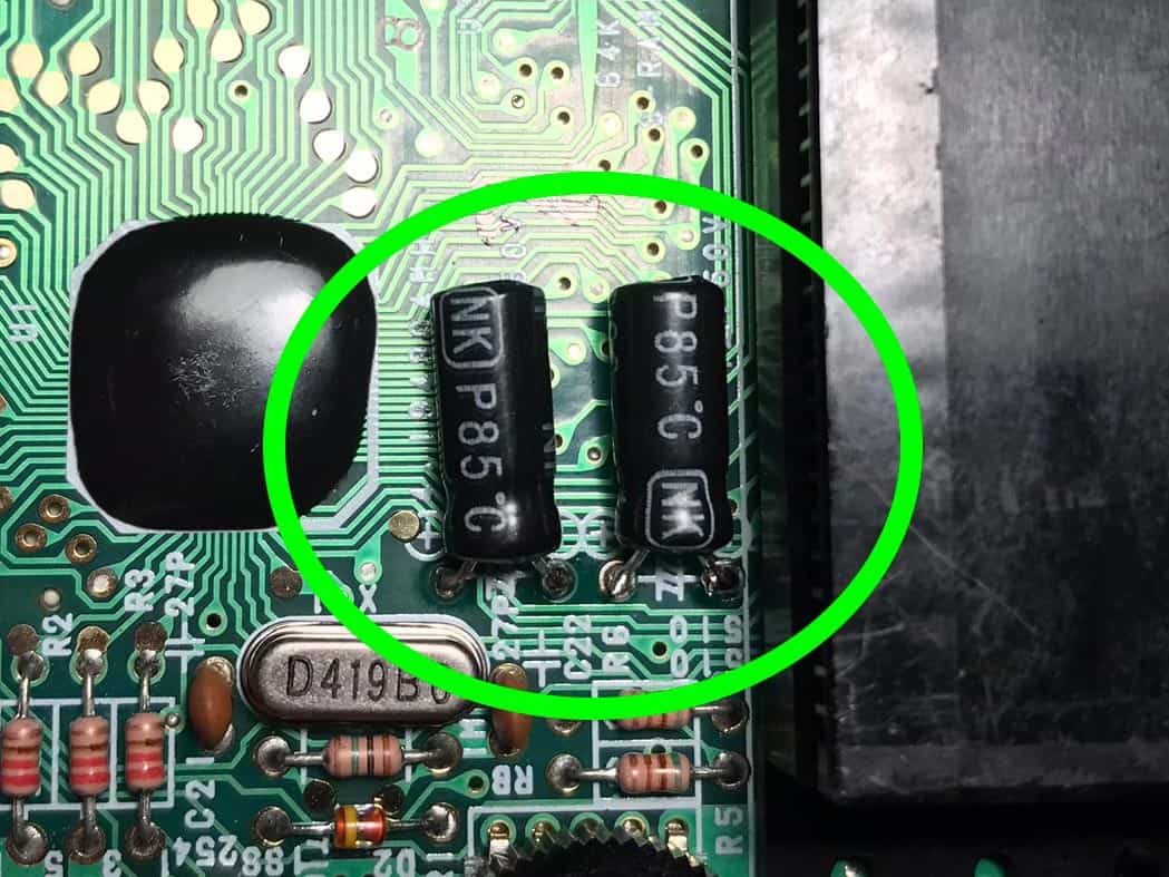
4. Success
New 10uF capacitors are soldered in place and the solder joints are looking good.
Bass mod completed.
How to do the decoupling capacitor mod on the power strip
This mod is done to improve sound quality after having installed the pro sound and backlight mod.
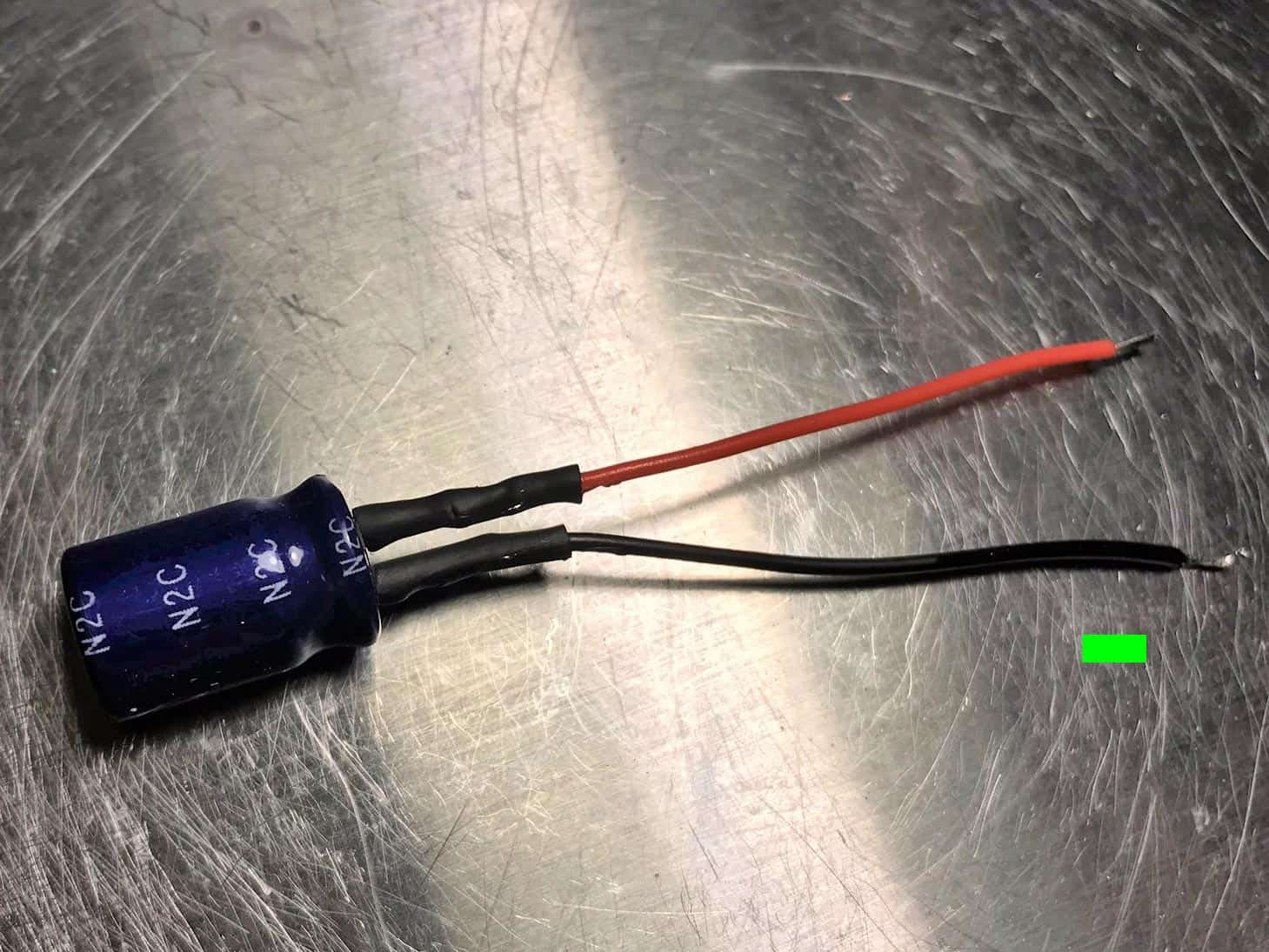
First, you need to get hold of an electrolytic capacitor in the range of at least 500-600 uF, although I recommend going for a 1000uF. I have tried different values and found that 1000uF produces the best results, in regards to the reduction of hiss and noise.
1. Solder wires to the capacitor
Start by soldering a black wire to the minus pin (the shorter pin) and then a red wire to the plus. Although not totally necessary I always also add a couple of shrink tubes to minimize the risk for shorts.
2. Solder the wires to the powerstrip
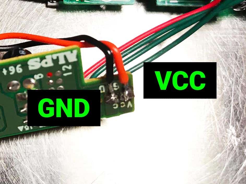
Locate the power strip. Solder the red wire to where it says VCC and the black wire to GND. Done!
Final results
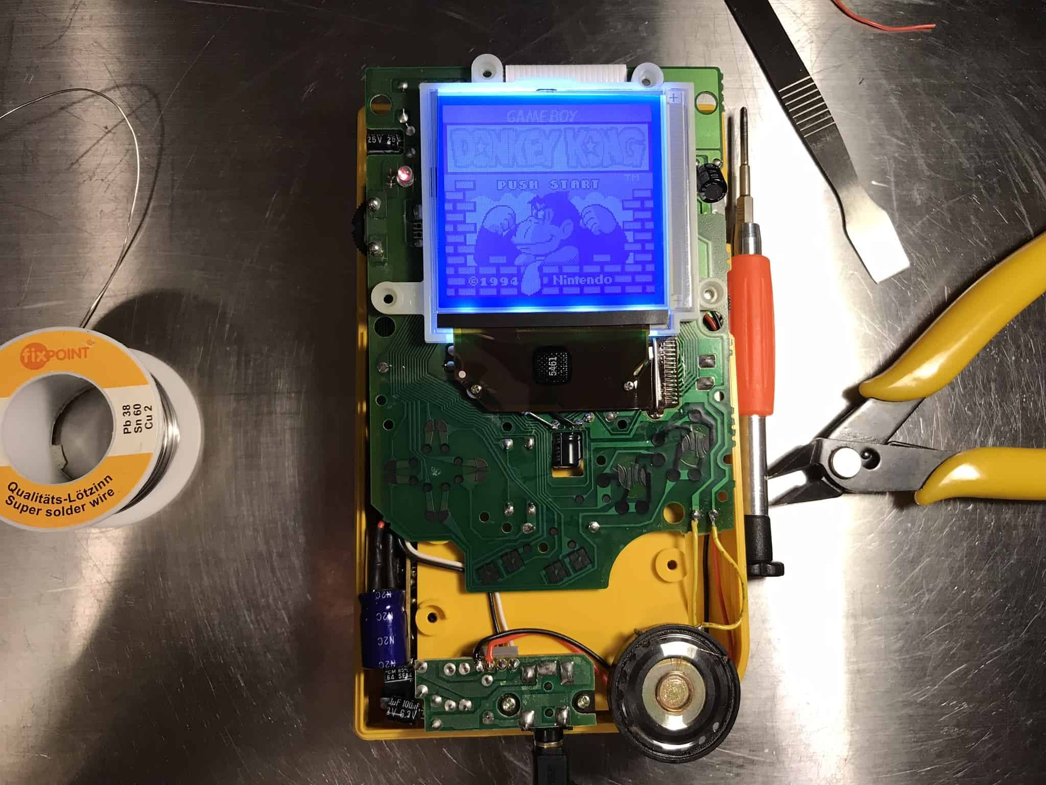
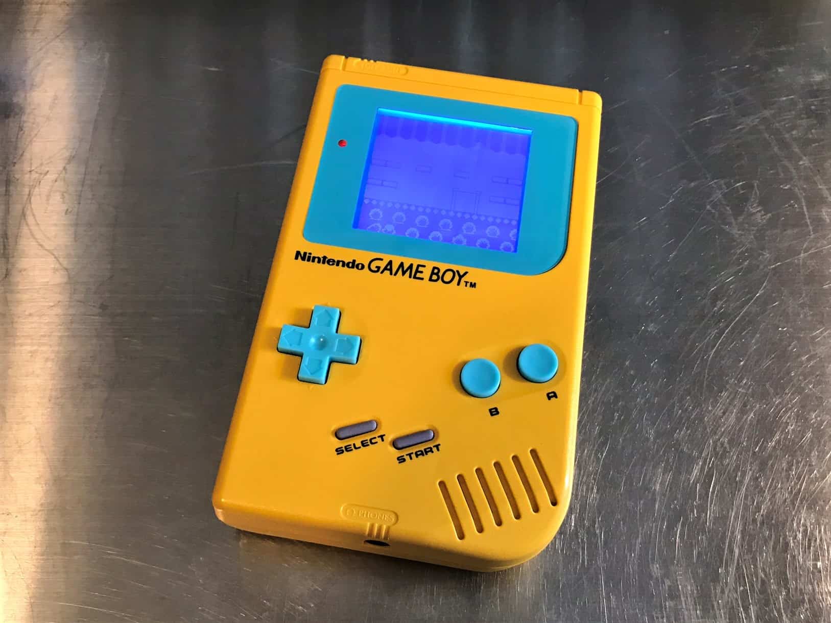
Before putting everything back together in the shell, make sure one last time that everything is working as it should. Put in a game and let it run for a while. When you are certain everything is OK, screw everything back together and enjoy your modded Game Boy.
I hope you enjoyed my modding guide. If you are having any problems or perhaps suggestions for things I could add to this guide, please let me know on my Facebook page. Also, I would be super happy if you could please head over to my Spotify page, and click Follow. Thank you in advance. It really means a lot to me.

